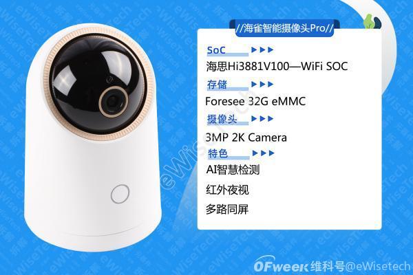
With the popularization of smart devices, smart cameras have become a must-have smart home device for all manufacturers. eWiseTech has also dismantled many models, and today is also a smart camera-Huawei Smart Selection Puffin Smart Camera Pro.
Disassembly steps
Tear off the bottom information label, you can see the screws on the bottom shell, unscrew the screws, and open the bottom shell.
After opening the bottom shell, you can see that there is a power cord connected to the small USB board. The small board is fixed with two screws. Remove the USB board to separate the bottom shell. A black tape is attached to the position of the power cord interface.
Turning over the camera body, you can see that the bearing of this camera is directly fixed on the inner support. There is a black limit switch at the bottom, which is used to limit the movement angle of the camera.
Screw the inner support and the shell, unscrew the screw, and remove the inner support. There is an FPC cable between the upper part of the inner support and the camera. Disconnect the ZIF interface and remove the inner support module.
Except for the disconnected camera cable. There are also four interfaces on the board, which are respectively connected to limit switches, motors, USB boards and speakers. Disconnect the interface, unscrew the screws, and separate the internal support modules.
Unscrew the fixing screws of the sphere part of the camera and the housing, and take off the housing. There is a piece of black foam glue above the buttons inside the shell.

The two sides of the camera sphere are fixed with two screws respectively. After unscrewing the screws, use a crowbar to pry the buckle and open the sphere.
Half of the sphere fixes the main board and the camera, half fixes the motor, disconnects the motor interface, and separates the shells on both sides.
The motor is fixed by two screws, and the motor can be removed by unscrewing the screws.
Unscrew the screws on the motherboard and take off the motherboard. On the side of the main board close to the motor, you can see two limit switches with a vertical rotation angle.
A set of screws of the lens and the motherboard are shared, so after the motherboard is removed, the lens part of the camera can be directly removed from the back of the motherboard. The CMOS of the camera can be seen, and there is a transparent double-sided tape around it, which should be used to fix the lens to prevent Into the ash.
There is a set of connecting wires with the lens module on the back of the main board, which are used for the motor components inside the lens. Used to switch the infrared filter.
There are infrared light board and microphone in the shell. The microphone is fixed in the module with white glue, and the infrared light board is fixed with screws. The lens port uses a silicone protective ring to protect the lens.
In addition to six infrared lamp beads on the infrared light board, there is also a light sensor.